Example1
This package contains the power system models used in Example 1 of the paper "Power System Modeling for Identification and Control Applications using Modelica and OpenIPSL"
Information
This package contains the power system models used in the paper "Power System Modeling for Identification and Control Applications using Modelica and OpenIPSL" by Luigi Vanfretti and Chrisopher R. Laughman, submitted for review to the IEEE CCTA 2024.
The models have the following dependencies:
- Modelica Standard Library v.4.0.0,
- Modelica_LinearSystems2 v2.4.0,
- DataFiles v1.1.0,
- DymolaCommands v1.16,
- LinearAnalysis v1.0.1,
- OpenIPSL v.3.0.1
The models were developed and tested with Dymola 2024X under MS Windows 11.
(c) 2024, Luigi Vanfretti, Rensselaer Polytechnic Institute, Troy, NY, USA and Chrisopher R. Laughman, Mitsubishi Electric Research Labs., Cambridge, MA, USA.
Package Content
| Name |
Description |
 Readme Readme
|
Summary: modeling aspects and how to use this package |
 References References
|
Reference papers. |
 Contact Contact
|
Contact |
 Copyright Copyright
|
Copyright |
 Base Base
|
Partial Models (for inheritance, not to be individiually simulated) |
 Interfaces Interfaces
|
Partial models for output interfaces. |
 PFData PFData
|
Records with power flow data to simulate various scenarios. |
 Analysis Analysis
|
Simulation and linearization models. |
 CustomComponents CustomComponents
|
|
 Utilities Utilities
|
|
Summary: modeling aspects and how to use this package
Information
The models in this package were originally developed using similar component models and parameters as the single-machine infinite bus (SMIB) model used in the Example 13.2 in [3], pp. 864-869, implemented using the OpenIPSL library.
This implementation has been carried out to illustrate Modelica and OpenIPSL features useful for identification and control applications [1,2], and as such, is set up a bit differently from models typically used only for simulation puroses in power system analysis. A similar implementation with much narrower scope (i.e., only time-domain simulation) is included in OpenIPSL, which can be found under: OpenIPSL.Examples.KundurSMIB
To meet the needs of the work in [1,2], the model was built with input and output interfaces as shown in the figure below (see more details in [1], Figs. 3 and 4).
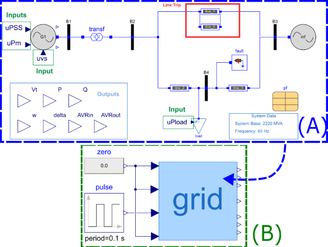
Let us first describe the figure enclosed by a dashed blue line, i.e. (A), this corresponds to the Example1.Base.Systems.gridIO model within this package:
- In (A), the whole single-machine infinite bus (SMIB) model is shown, it is composed by the main power plant (also called generator unit), G1, a transformer, trans, several buses, lines, etc.
- The inputs to the system are inclosed in a solid green line and labeled "Input(s)". They include, uPSS, uPm and uvs in the main generator, G1, and uPload in the load.
- The outputs are enclosed in a solid light-blue line in (A), and include, Vt, P, Q, etc. These are inherited from an output interface and linked to variables of the gridIO model within it's text layer.
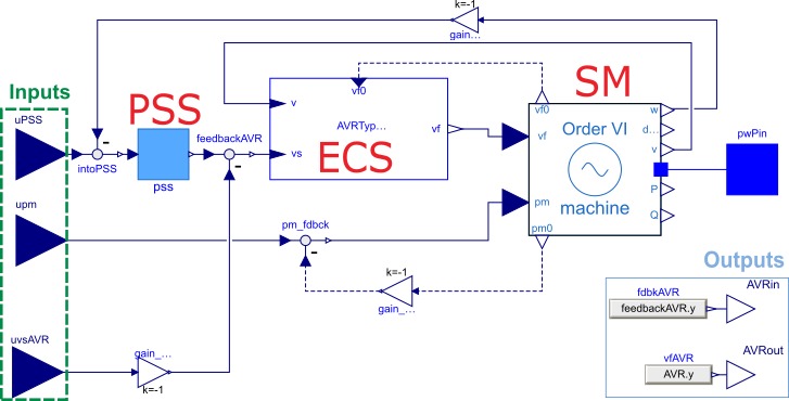
- The main generator unit, G1, is built from multiple components from OpenIPSL, as shown in the figure below, including a 4th order synchronous machine model, an excitation control system and a PSS. Comparing the figure below with the one in (A), it can be seen that uPSS provides a direct input to the PSS, uPm provides an input to the mechanical power reference of the machine, pm, and uvs provides an input into the error signal between the PSS and AVR. This is the point where an input signal is injected for closed loop identification as discussed in [2].
- The model shown in (A) can be used for both simulation and linearization purposes. For simulation, inputs have to be provided, as shown in (B), where the load input (uPload) is connected to a pulse, while the others are set to zero.
To get started using these models and facilitate simulation/linearization workflows, the Example1.Analysis package consists of three sub-packages that provide different model variants and functions to perform the following studies:
- Example1.Analysis.LinearAnalysis, provides models and functions to illustrate how to perform linearization on a model, simulate the linear model and compare it against the response of a nonlinear model. These tasks are automated executing the function LinearizeAndCompare, which will help to reproduce the results shown in Fig. 6 of [1]. See more information in the documentation/info layer of the function.
- Example1.Analysis.NonlinSimulationsMultipleInputs illustrates how to provide input signals to the model. The main model that can be used to reproduce the simulations presented in [2] is A_randomload_and_lowimpactmultisine. Running that model will help produce the data presented in Figs. 6 and 10 of [2]. To facilitate simulation and plotting of any of the model variants under this package, executing the function simulate_and_plot, will produce the plot below. To simulate other cases, the name/path of the model can be provided as a string input into the function, see more information in the documentation/info layer of the function.
- Example1.Analysis.RedesignedControllerVerification, is configured to simulate the response to an 8-cycle load disturbance and to compare the default PSS control design with the two redesigned controllers presented in [2]. There are three models with different control designs that need to be simulated and compared, to facilitate analysis and reproduce a similar figure to Fig. 10 in [2], the C012_simulate_plot_compare function can be executed. See more information in the documentation/info layer of the function.
To better understand how the model is built please refer to [1]. Meanwhile, to find the applications in identification and control where this model was used, you can find more details in [2].
Copyright
Information
(c) 2024. All rights reserved.
Luigi Vanfretti, Rensselaer Polytechnic Institute, Troy, NY, USA and Christopher R. Laughman, Mitsubishi Electric Research Labs., Cambridge, MA, USA.
Automatically generated Wed Mar 13 11:30:32 2024.
 Example1.Readme
 Example1.Copyright